You can maintain diagram layers from the Define Diagrams screen at the top right of the toolbar, or from the Plan Generation landing page. Any changes you make to diagram layers will be automatically updated in Layout Plan Sheets once you have saved your selections.

If you have spatially selected any diagrams in Define Diagrams when you open the Maintain Diagram Layers panel, the Individual user defined diagram option will only be editable for the selected diagrams. De-select the diagrams in Define Diagrams to see options for all Individual user-defined diagrams.
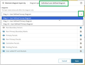
You can maintain diagram layers for all diagrams of a specific type (for example all user-defined primary diagrams), or for an individual user-defined diagram (for example diagram AA).
Maintain diagram layers by Diagram type
Left-click the drop-down menu under Diagram type to select and maintain layers for:
- System Generated Primary Diagram
- System Generated Survey Diagram
- System Generated Non Primary Diagram
- User Defined Primary Diagram
- User Defined Survey Diagram
- User Defined Non Primary Diagram.

Maintain diagram layers by Individual user-defined diagram
Left-click the drop-down menu under Individual user defined diagram to select and maintain layers for an individual diagram, for example Diagram A – User Defined Primary Diagram.
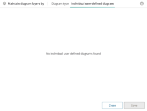
If you have not defined any diagrams, the panel will display No individual user defined diagrams found.
Once you have defined 1 or more diagrams in Define Diagrams, the diagrams will appear here.
Layer types are related to the diagram you’re working with
Each type of diagram has its own set of:
- mandatory layers that must be shown (you can’t turn these layers off)
- optional layers that you can turn on or off as needed (set to off by default).
The available layers change as you select each different type of diagram.
For example, the System Generated Primary Diagram layers are:
Mandatory – these will always show:
- Primary Boundary Marks
- Primary Parcel Dimensions
- Primary Parcels.
Optional - Select the layers you want showing from:
- Non Primary Boundary Marks
- Non Primary Parcel Dimensions
- Non Primary Parcels
- Centreline Parcels
- Existing Parcels
- User Added RT and Abuttals.
For details of available diagram layers:
To turn a layer on, left click on the Show/Hide icon next to the layer name.

The icon will change from Hidden to Shown. To turn the layer back off, left click again on the icon.

Any layers you turn on will be included in your diagrams in Layout Plan Sheets.
Layer dependency:
If you turn on a primary or non-primary parcel or dimension layer, the corresponding mark layer will also be turned on.
Labels for diagram layers
The layer labels will appear on the layout plan sheets as text and symbols.
Labels for each layer default to being displayed as you turn the layer on, but you can choose to hide them here.
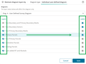
To turn the labels off for a layer that is showing, left-click on the tick box to the right of the layer.

The box will change to unticked, and the labels for this layer will not show on the selected diagram on the layout plan sheets. To turn them back on, left-click again on the empty label tick box for the required layer.
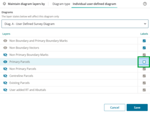
The Existing Parcels layer has Boundary Lines ON as default when the layer is turned on. Left-click the Boundary Lines ON box to untick this option if you want to show labels (appellations) for any existing parcels but hide the boundaries.

The box will change to Boundary Lines OFF. You can left-click again to turn the existing parcel boundary lines back on.

Save and close maintain diagram layers
Once you have added your layers and labels for a diagram type or individual diagram, select Save to save your selections.

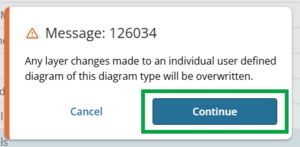
For Maintain diagram layers by Diagram type, when you select Save, a message will appear advising that any changes made will overwrite the Individual user defined diagrams if you continue. Select Continue to save your changes.
Example: You had maintained individual Diagram AA - user defined Primary diagram, then maintain User Defined Primary Diagrams. This will overwrite the saved settings in diagram AA.
If you have made changes to any diagram layers and try to shift away to a different diagram type or individual user defined diagram before saving, a pop-up box will appear warning you about unsaved changes. Select Save to save or Discard to continue without saving.

Once you have saved all your changes to diagram layers and labels, the Maintain Diagram Layers panel will display All layers up to date.
You can safely left click on Close to close the panel and continue with Layout Plan Sheets or Define Diagrams.

Diagram layers
Survey diagram layers
These tables list the mandatory and optional layers available to each survey plan diagram produced in Plan Generation. These layers display in the Survey Sheet layout pages in the Layout Plan Sheets screen.
System Generated Survey Diagram
| Layer | Label | Layer Optional |
|---|---|---|
| Non Boundary and Primary Boundary Marks | Mark name | No |
| Non Boundary Vectors | Bearing, Distance | No |
| Non Primary Boundary Marks | Mark name | Yes |
| Primary Parcels | Appellation, Area | Yes |
| Non Primary Parcels | Appellation | Yes |
| Centreline Parcels | Appellation | Yes |
| Existing Parcels | Appellation /Road name where applicable | Yes |
| User Added RT and Abuttals | None | Yes |
User Defined Survey Diagram
| Layer | Label | Layer Optional |
|---|---|---|
| Non Boundary and Primary Boundary Marks | Mark name | No |
| Non Boundary Vectors | Bearing, Distance | No |
| Non Primary Boundary Marks | Mark name | Yes |
| Primary Parcels | Appellation, Area | Yes |
| Non Primary Parcels | Appellation | Yes |
| Centreline Parcels | Appellation | Yes |
| Existing Parcels | Appellation /Road name where applicable | Yes |
| User Added RT and Abuttals | None | Yes |
Title diagram layers
These tables list the mandatory and optional layers available to each title plan diagram produced in Plan Generation. These layers display in the Title Sheet layout pages in the Layout Plan Sheets screen.
System Generated Primary Diagram
(Based on the diagram extents of the System Generated Survey Plan Primary Diagram)
| Layer | Label | Layer Optional |
|---|---|---|
| Primary Boundary Marks (reduced symbology) | None | No |
| Primary Parcel Dimensions | Bearing, Distance | No |
| Primary Parcels | Appellation, Area | No |
| Non Primary Boundary Marks (reduced symbology) | None | Yes |
| Non Primary Parcel Dimensions | Bearing, Distance | Yes |
| Non Primary Parcels | Appellation | Yes |
| Centreline Parcels | Appellation | Yes |
| Existing Parcels | Appellation /Road name where applicable | Yes |
| User Added RT and Abuttals | None | Yes |
System Generated Non Primary Diagram
(Based on the diagram extents of the System Generated Survey Plan Non Primary Diagram)
| Layer | Label | Layer Optional |
|---|---|---|
| Boundary Marks (reduced symbology) | None | No |
| Non Primary Parcel Dimensions | Bearing, Distance | No |
| Non Primary Parcels | Appellation | No |
| Centreline Parcels | Appellation | No |
| Primary Parcels | Appellation, Area | Yes |
| Existing Parcels | Appellation /Road name where applicable | Yes |
| User Added RT and Abuttals | None | Yes |
User Defined Primary Diagram
(Based on the diagram extents of the User Defined Survey Plan Primary Diagram)
| Layer | Label | Layer Optional |
|---|---|---|
| Primary Boundary Marks (reduced symbology) | None | No |
| Primary Parcel Dimensions | Bearing, Distance | No |
| Primary Parcels | Appellation, Area | No |
| Non Primary Boundary Marks (reduced symbology) | None | Yes |
| Non Primary Parcel Dimensions | Bearing, Distance | Yes |
| Non Primary Parcels | Appellation | Yes |
| Centreline Parcels | Appellation | Yes |
| Existing Parcels | Appellation /Road name where applicable | Yes |
| User Added RT and Abuttals | None | Yes |
User Defined Non Primary Diagram
(Based on the diagram extents of the User Defined Survey Plan Non Primary Diagram)
| Layer | Label | Layer Optional |
|---|---|---|
| Boundary Marks (reduced symbology) | None | No |
| Non Primary Parcel Dimensions | Bearing, Distance | No |
| Non Primary Parcels | Appellation | No |
| Centreline Parcels | Appellation | No |
| Primary Parcels | Appellation, Area | Yes |
| Existing Parcels | Appellation /Road name where applicable | Yes |
| User Added RT and Abuttals | None | Yes |