
There are 2 types of vector:
- right line
- arc.
You can enter vectors sequentially or radially. Right line vectors can also be entered as bearing-only vectors or distance-only vectors.
In the Vectors panel, the 2 types are differentiated by the symbols between the two numbers in the Marks column, and the 'Arc' suffix in the distance field.

Right line vectors
What to do
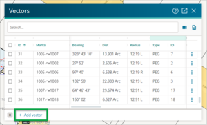
To add a vector, first select the Vectors icon from the Workflow toolbar.
This will bring up the Vectors panel.
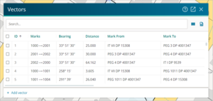
If you adopted any existing vectors for your survey, they are listed in this panel.
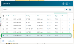
Select the + Add vector button at the bottom of the Vector panel.
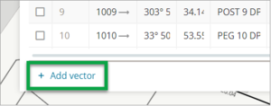
- When you click the + Add vector button at the bottom of the Vector panel a new row is added to the Vector panel. The Mark From and Mark To references default to a number (such as 1000 and 1001), and other fields also display default values. Change these values if required.
- If an existing vector has been captured, clicking the + Add vector button will add a new row at the bottom of the vector list, with most fields automatically populated from the last captured row. The Mark From field will be populated with the Mark To reference from the row above, and the Mark To reference will be populated with the next available default number.


The new row will copy most of the information from the previous row, including the Radius. This means if the previous row was an arc vector, the new row will be created as an arc vector, and if the previous row was a right line vector, the new row will be created as a right line vector.
If you want to change an arc vector to a right line vector, simply delete the radius value.
- Complete the details of the vector.
- Complete other details as needed.
- If the Mark To mark is a new mark or if it is an adopted mark requiring more information, complete the details of the mark in the appropriate field. Use the Marks panel to edit other mark details.
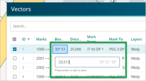
- When adding new vectors in the Vector panel, you can use Enter, Tab or the arrow keys to move between fields.
To bring an adopted survey into terms with a new survey, you may need to apply an adjustment to some bearings. You can edit a vector by double clicking on the bearing field and then making changes. Your changes are saved automatically.
- If adopted vectors have been captured with no bearing correction, the correction will show as 0° 00’. If you change the bearing correction in the Survey details panel, any adopted vectors you add after this will apply the new bearing correction. However, the correction is not automatically applied to adopted vectors that were captured before you entered the bearing correction. To apply it you need to manually reselect the CSD Bearing Source.
- If you have manually captured vectors from the spatial view, you need to edit these bearings in the Vector panel.
- Each measured vector is to have the type of equipment recorded in the Equipment column (Cadastral Survey Rules 2021 rule 78(d)).
Double left click in the equipment field to show the list of available equipment options.
These options can also be used for adopted vectors.
Unknown is used for calculated or adopted vectors where it is uncertain how the measurement was derived.
Old adopted is used where the adoptions do not fit the current accuracies and you know they were derived from older survey equipment such as Gunter's chain and vernier theodolite. Selecting this equipment type is a method to slightly down-weight the adoptions and help allow better testing of remaining vectors.

Arc vectors
What to do
Select the Vectors icon from the Workflow toolbar.
This will open the Vectors panel. Select the + Add vector button at the bottom of the panel.
When you select the + Add vector button at the bottom of the Vector panel, a new row is added to the list in the Vector panel.


The new row will copy most of the information from the previous row, including the Radius. This means if the previous row was an arc vector, the new row will be created as an arc vector, and if the previous row was a right line vector, the new row will be created as a right line vector.
If you want to change an arc vector to a right line vector, simply delete the radius value.
- Update the following fields with the appropriate information:
- Start and end mark IDs in the Marks field.
- Add the chord bearing for the arc in the Bearing field.
- Add the arc length in the Dist field.
- Add the arc radius in the Radius field.
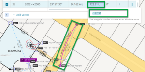
If you enter a +ve number, the arc vector will be on the right-hand side of the chord bearing. The radius will be displayed in the Radius field with an R suffix.
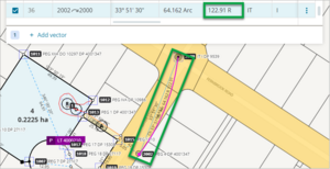
If you enter a -ve number, the arc vector will be on the left-hand side of the chord bearing and the radius will be displayed in the Radius field with a L suffix.


Populate the Brg Type field with the appropriate option. If the arc vector is adopted from a previously approved plan or document, enter the source reference in the Brg Source field.
The Dist Type and Dist Source fields are not editable for arc vectors.